
|
|
|
Home |
This PageThese thoughts are mainly just my own discoveries made while building my Rush. I would very much like to collect other Hints and Tips from other Rush builders and owners. Hopefully we can build up a useful resource covering more than just the V8 IRS model. Please email me (duncan at duncan-hurst.co.uk) with any build ideas you may have, large or small, and I'll include them here. I will acknowledge all contributions. Thanks to:
for their contributions. ContentsMy Hints & Tips are gathered under the following headings. Please click on one or browse the full list below. Mandatory Disclaimer:I have done my best to make these tips useful and accurate. However, you must use your own judgement when following this advice as your circumstances may differ. I cannot be held responsible if things go wrong as a result of doing things as suggested here. What you do is what you do! 1. Working ConditionsLightYou can't have too much of this. I improved my garage's single light bulb with four 4-foot fluorescent strip lights, spread around the edges of the ceiling to cast light not only on top of the car, but down the sides as well. An inspection lamp will be useful too. I made one from a cheap halogen security lamp, screwed to a wooden base. PowerYou'll be using power tools frequently. Having several double sockets spaced around the place avoids having to use extension cords and all the attendant walking around, tripping up etc. I wired in a ring of five double sockets, one over the workbench and one opposite each wheel of the Dax. TrestlesHigh trestles - Good, low axle stands - Bad! Get the whole chassis about 30 inches up on a pair of sturdy trestles if possible. I made some out of wooden studding (4" x 2") and they happily took the whole weight of the car with two people sitting it. StorageLots of shelves. Get stuff off the floor. So saying, the space under the chassis is useful for bulky things like seats. Containers are good. I got hold of lots of Quality-Street-type tins and used them, well labelled, to store small items. SafetyElectricity burns, tools cut and pierce, solvents affect the brain. You know all this - be safe while you work. Your safety is your responsibility. Cautionary tale: once or twice I cut my hand sufficiently badly that I couldn't do any useful work with it for a while. That was frustrating to say the least and slowed the build down (and it hurt!). 2. MaterialsCleaningI got through many, many rolls of cheap kitchen roll. It's better to clean something up and chuck the paper away than to mess around with bits of greasy rag. I got a box of 100 latex gloves. These are great when using solvents, paint, grease etc. but they quickly turn into thin rubber shreds if you handle mechanicals with them. Get a pair of thick leather gloves for those dirty donor parts. They're very cheap in the DIY shops. Nuts & BoltsIf you're at a kitcar show and see one of those stands selling huge bags of assorted nuts & bolts - GET ONE! I bought a big bag of assorted plated UNF nuts, bolts & washers. It weighed several pounds and cost 15. I didn't think I'd get through much of this bagful, but at the end of the build at least half were gone. Metric would be as good as UNF, especially if you are using a Ford engine. If you've got a Rover V8 engine, a bagful of UNC nuts & bolts would also be a good idea. 3. Build OrderDon't necessarily believe the manual. It tells you to do things in an awkward order sometimes, such as putting the side panels on before the engine goes in. It's much easier the other way around as you have access to useful things like the engine mounts! Since my garage isn't very wide, I chose to keep the suspension off the car for as long as possible, to give more walking-space around it. This worked out very well, with the car going from main body-unit on trestles to driving car in under a week. My suggested build order is: (With chassis upside down):2 floor panels & 2 long triangular floor infill panels (With chassis the right way up):Passenger footwell end panel 4. ChassisPowder-CoatingIf your chassis is powder-coated, there will be powder-coating inside all the threaded holes in the chassis. Clean the threads out with a tap or a spare bolt with slots cut along it. My seatbelt eye-bolts were very tight in their bushes until I had worked a bolt through them a few times. The V8 ChassisDax modify the V8 chassis to allow more clearance around the cylinder heads. This puts the steering column very close to the chassis and the brake pedal. This is normal. Lifting pointsThe nose cone hoop makes a fine lifting point, as does the roll-bar at the back. Both can be used to lift one end of the car when complete. 5. SuspensionWishbonesThe rubber wishbone bushes will press nicely into the wishbones using a little washing-up liquid as a lubricant and a G-clamp plus suitably large socket to do the pushing. Cam Caine says "Here's a tip from the Triumph fraternity
re rubber wishbone bushes - (metalastic things) - put them in the fridge for a few days
before fitting them. This stiffens up the rubber and makes them easier to fit -
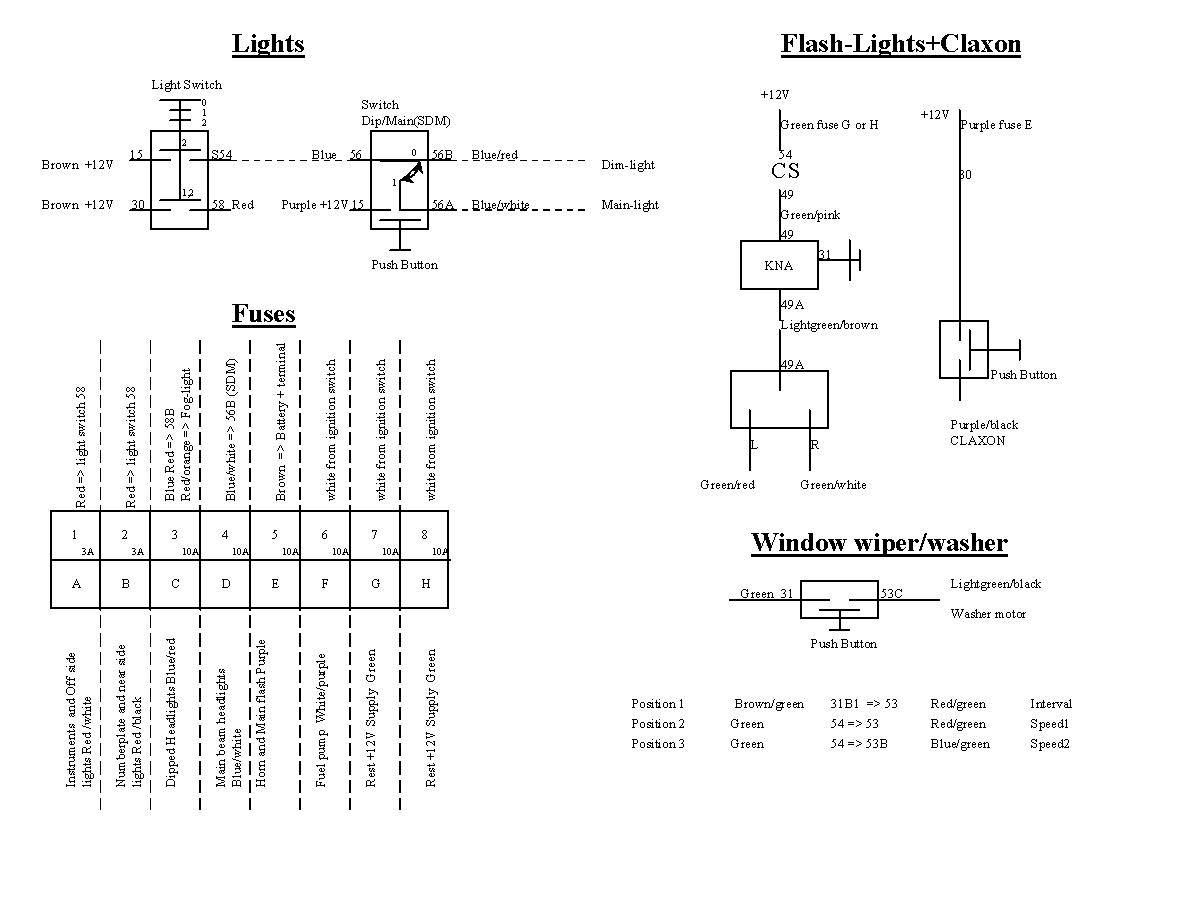
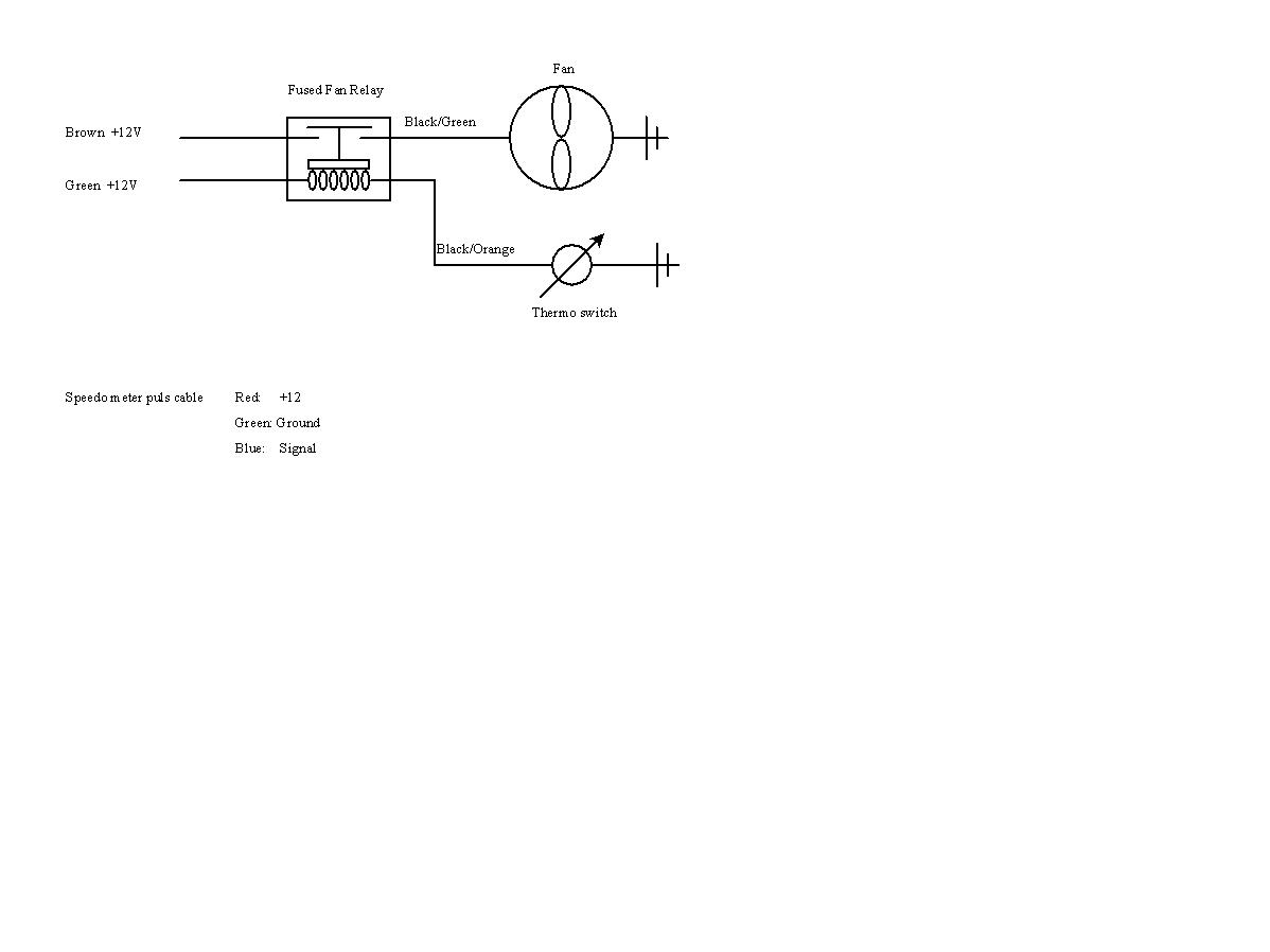
apparently ......... Dean says "Swarfega to insert the suspension bushes, use a vice and suitable sized sockets." The rear wishbones have tapered holes for the uprights' ball joints. Make sure you get the wishbones the right way up. Dean says "Assembly of the rear suspension is easier if you follow the manual (probably the only thing that is!). The uprights are left and right handed!" Wishbone boltsThe front lower wishbone bush bolts are very difficult to get in and tighten up, due to the restricted space between the lower chassis rail and the side panel. I used the cap-head bolts in these locations. This allows you to hold them with an allen key while turning the nyloc nut with a spanner or combination of socket extensions. The rear lower wishbone front bush bolt heads will be trapped by the GRP tunnel. Put the bush housings in place and get the bolts torqued up (with the housing held horizontal) before the tunnel goes on. Front Cycle Wing BracketsDave Sawdon has reminded me that the triangular plate that holds the lower ends of the front wing stays needs a bit of fettling. It fouls the lower balljoint nut and I had to grind an indentation in its lower edge to clear the nut. The triangular plate is bolted to the Cortina upright, but spaced off with three tubes slipped over the bolts. As supplied, the tubes are all the same length and have square ends. I had to grind a couple to sit flush on the inside of the upright and hold the plate parallel to the upright. Without this, the wing stays rubbed on the inside of the tyre, although a bit of judicious bending would cure this. Dave had to have his wing brackets re-chromed, as the originals were going rusty due to trapped pickling acid. A clean-up, re-weld, polish and re-chrome sorted his out. SettingsI had to have the rear springs set at their lowest ride height to get the back end down to Dax's stated 170mm under the chassis rails. I found I could leave the front springs at maximum ride height and still be in the stated 130-150mm range. This will be good for maximum sump clearance. Gary at Dax recommended me to soften the rear shock absorbers fully and have the fronts on only 2 'clicks' from full soft. 6. Aluminium chassis panelsThese will need trimming here and there to get a good match with the chassis tubes. They are all supplied flat and some need bending. I did this by gripping two lengths of angle-iron in a Workmate and bending the panel between them by hand. Really tight bends can be achieved by dressing them with a block of wood and a hammer. Don't bend them back and forth too many times, or they will crack. Dave Sawdon says "I bought the chassis unpainted and assembled the car using self tapping screws instead of rivets, just say six in each of the bottom panels. This enabled me to drill all the rivet holes ready for assembly. As I progressed with the build this highlighted any problems with panels, brackets, areas where the engine was too close, and I was able to rectify prior to paint. It also means that all the swarf can be cleaned out from between the panel. This could be done even if the chassis was painted first." Shoulder panelsThese are the hardest panels to fit, due to the many bends needed to make them lie flat on the chassis rails in this complicated area. I made cardboard templates first, and got them to fit properly, before I bent and trimmed the real thing. See my picture of a cardboard template to see where I put flanges and bends. Note: these panels are now supplied pre-formed in fibre-glass and are hopefully a lot easier to fit. Hidden VIN numberWithout giving too many secrets away, Rush builders will notice a third copy of the VIN number stamped into the chassis. This will be hidden in the completed car and can presumably be used as a double-check of a car's identity if the visible VIN numbers are changed. There is usually a panel over this place on the chassis, so remember not to put rivets through this bit of panel and through the VIN number. 7. BrakesSee also SVA Issues. Fixed brake pipesDon't route the rear main brake pipe as shown in the manual. It won't reach! Route it from the rear 3-way union, along the top of the round diagonal tube on the driver's side of the tunnel, along the inside of the tunnel on the side of the bottom rail, across the bottom of the driver's footwell front and up the outboard side of the driver's footwell front. Dax route their pipes this way. I followed the manual (first time) and found the rear main pipe was about 3 inches too short. Taking the diagonal route adds back this lost length. According to Brian Johns, all the brake threads are M10 x 1 except the master cylinders which are a UNF thread. Flexy brake pipesDean says "At all four corners check the movement on the flexible stainless brake hoses and make sure none of them can touch any part of the dampers or springs." GrommetsThe idea of these is to prevent the front flexy brake pipes rubbing on the front top wishbones. These grommets cannot be pushed onto the braided hose over the end fittings. I did try for a while! Cut them with a sharp knife and use superglue or Wurth adhesive to re-stick them. HandbrakeI used velcro to attach the handbrake gaiter to the top and bottom faces of the cross-rail under the front of the scuttle. Works fine! John says "If you struggle trying to fit your handbrake cable rear section, check that it is not a Kamala one. The Rush one has approx 39" of inner cable showing when the outers are pulled as far apart as possible. The Kamala one has 10". Boy did I sit and think and fight and curse that. Appears I got the wrong part in my kit." Fluid ReserviorMount this as high as possible, remembering where the underside of the bonnet is. My SVA tester only just passed my reservoir because he wanted it to be higher than the brake master cylinders. I made an aluminium bracket to hold the reservoir high off the battery shelf. The washer bottle conveniently fastened to the front of this bracket as well. Dean says "The standard brake fluid reservoir that Dax supply is an old Jag one and it leaks, same as it did on the Jags! No matter how much you tighten the lid, put a new O-ring in, whatever, it will still leak. Europa Spares do a neat replacement." 8. Bodywork panelsSide panelsI had the aluminium side panels. I don't know as much about the GRP ones. See Dean's comments below about packing out the gap between the lower flange of the GRP sidepanels and the floor. This gap didn't exist with my ali panels. CuttingThe folded-over front edge of the panels had to be removed in places to allow clearance for chassis brackets. I used a jigsaw with a fine-toothed blade and then files to cut the four oval holes for the exhaust downpipes. Dean says "Side panel holes for front wishbones needed to be tidied and squared but watch there is enough clearance for those extreme suspension movements." SpacingThe side panels needed to be held away from the chassis sides slightly, in order to line up with the sides of the scuttle. I fastened the sides, top and bottom, at the right spacing under the scuttle and then pulled them tight to the chassis at the front and back. The thickness of the side panels needs to be filled with something if you intend to carpet the interior. I used 1 inch thick foam from a local upholstery shop. Gary at Dax panels the inside with thin aluminium sheet. Dean (GRP sidepanels) says "Side panels will need spacers between their lower edges and the chassis rail to which they will be fixed. Washers can be used but I used nuts just slightly larger than the fixing screws. Once the gap is filled with sealant they can’t be seen anyway." BackrestCuttingThe big hole for the propshaft will need extending in a few places to allow the rear brake pipe and wishbone mounts to pass through. The curled-over top of the backrest had to be ground considerably to fit down over the rear shock absorber top mounts. This area is hidden when the boot box drops in so the edges don't need to be perfect. FillingWith the backrest panel now being GRP, rather than aluminium as previously, it can use some extra support where it passes over the diagonal tubes behind it. The gap here varies from nothing to about an inch. I filled it in stages with black polyurethane mastic and it now provides better support to the seat backs. Transmission TunnelFitThe tunnel will need a bit of chopping where it passes over the floor bracing 'L' sections, if it is to sit flat on the floor. Mine didn't sit flat against the backrest panel. There was a gap of 0.5 inch at the top. Once filled in and carpeted over, the seat backs seem to fit over it well enough. SealingIf you ever want to remove the tunnel (and you might well), don't glue it down with BD or similar - you'll never get it off again! However, you should waterproof the joints. I used a flexible, non-hardening, weatherproof, cheap mastic otherwise known as glazier's putty! Putty comes in a tube nowadays and can be squirted into place using a normal mastic gun. I also used self-tapping bolts to hold the tunnel to the chassis rails at floor level. Two large-head rivets fasten it to the backrest as bolt-heads would create 'budgies' in the carpet. If the tunnel has to be removed, just drill these out. ScuttleDean says "Leave plenty of spare on the wing beading for the returns under the scuttle edges. It’s hassle otherwise and a major area for being on show." Master Cylinder ClearanceA large rectangular hole must be cut in the front of the scuttle, to allow space for the back ends of the brake (and clutch) master cylinders. There is a 'sandwich box lid' of GRP which backs this hole. I found this piece didn't give enough depth to the hole, so I built up a few layers of Wurth adhesive (and let it dry) round the edges of the 'lid'. When finally glued in place, the extra thickness of adhesive gave an additional 0.5 inch of depth, which was just enough. I cut the scuttle hole smaller than the inside of the 'lid' by about an inch all round. This allows the edges of the hole to be trimmed with clip-on edging (as used on the front wings) without interfering with the glued-on 'lid'. Rear TubThe manual tells you to bolt the front edge of the undertray to a lateral chassis rail, the one at the front of the fuel tank. Mine wouldn't reach the rail and it would bend the GRP quite a bit to do so. Gary advised me to rivet the undertray to the rail behind the fuel tank. This left the front edge flapping around a bit, so I trapped it under the heads of some self-tapping bolts & washers which I could just get into the front of these two rails. Dave Sawdon says "I put two joggled brackets to hold the front edge of the tub which were welded in place and two inch by inch angles welded to each end of the tank mounting frame and bolted through the bottom of the tub." Dean says "For my boot tub I made up two straight brackets to fix the front edge of the underside of the tub, these were riveted to the chassis to secure this edge. From a piece of sheet aluminium the same gauge as the floor panels a simple rear undertray has been made. This bolts to the chassis where the floor panels finish and to the underside of the boot tub using its bolts to the chassis. Keeps road crap out and looks neat from the rear. Side plates to finish will be added. In order to make the boot box removable I used M5 bolts which screw into butterfly type plasterboard fixings. These fixings are spread out and have their "wings" countersunk riveted into the rear body tub." Nose coneThe back end of the nose cone was about 0.5 inch too narrow for my chassis. This is another good reason to ensure that the side panels are tight to the chassis at this point. I could just get a small bolt (no nut) through the nose cone flange and into the chassis rail top, to 'spread' the back corners of the nose apart a little. This also holds the nose in place when you take the bonnet off. The bulges on the sides of the nose cone foul the front SVA bars if you attempt to hinge the nose cone using bolts in its lower corners. No obvious solution except to remove the SVA bars :-) BonnetI had the aluminium bonnet and had to trim it to length, but it was already a shade too narrow in the width department. If you have an aluminium bonnet (or even if you don't), consider glueing the wing piping to the front and back edges of the bonnet instead of the scuttle and nose cone. This will give a protected edge to stand the bonnet on and also means that a carelessly-handled bonnet doesn't scratch the bodywork with a sharp corner. Chris Cocklin says: "I used Wurth to fix a 1" x 1/2" x 1/16th thick alloy angle ( B&Q ) along each side of the bonnet to keep both sides nice and straight, this gives you a return of 1/2" so the bonnet sits on the top of the side panels after trimming. This also allows you good anchorage for what ever locking system you decide to use. I used Dzus 90 degree twist cam-locks on my current Rush (R.S components) & over-centre catches on my last one. If you use over centre-catches you can get a lot more tension with this system without deforming the alloy bonnet. I think you will also find the black wing piping that you glued on with Wurth will come off in no time if you don't use the above system. [Duncan's note: I actually used contact adhesive here but, yes, it has started to come away in places]. I used sheet metal edging - you can get this from Woollies and the like. This is a U-section rubber with an internal grip and comes in varying sizes. I used 5/16" so you do not see the difference between the wing piping." Rear WingsThe fit of these is quite critical. The front corner must be level with the bottom of the side panel. The back corner must be level with the bottom of the rear tub. The inner edge of the wing must cross the side panel-to-rear tub joint closely enough to hide all of the back edge of the side panel, but not so much overlapped that you can see the wing flange from inside the car. It is not possible to get an even gap all round the tyre. The gap at the front will be tight and the gaps at the top and rear will be larger. I believe it's worse with the narrow (225 section tyre) wings than with the wide (245/255 tyre) wings. I ground away the return flange inside the wing aperture where the gap was narrowest. The big flange on the inner edge of the wing isn't quite at right-angles to the wing top, the angle is a bit acute. This has a tendency to pull the wing inwards and downwards when the flange is bolted to the body tub. I packed a few washers on the securing bolts, between the flange and the tub, and this encouraged the wings to keep the gap in front of the tyre open. I ended up with about a finger's width of gap at the narrowest point, opening smoothly to about 1 inch behind the tyre. Dean says "Depending on how the rear suspension is set up the rear tyres may touch the insides of the rear wings during full suspension travel. Fully loaded up with two large people it was necessary to remove some of the return on the wing for tyre clearance." Front WingsSee also Front Wing Brackets. Stick them on with Wurth adhesive. Rough up the wing stays and the underside of the wings first. When the initial globs of glue have dried, smear lots more over and around the joint. I stuck mine on in a fairly rearwards position, to try to catch the crud thrown up by the tyres before it hit the rear arches. However, the bottom edges of the wings now oscillate rapidly from side to side at certain speeds. A more forwards position may help here, as the amount of unsupported wing at the back will be reduced. I may have to make an extra support on each side to firm up the wings. I can then re-fit my home-made mudflaps as well, which caused the oscillations at all speeds before! 9. SteeringWheel sizeI use a 12 inch Mountney wheel and find it very comfortable. Much smaller would make the steering too heavy. Larger and you may not be able to get in! ColumnThe steering column will come very close (2-3mm) to the round chassis tube running from the inboard-top of the driver's footwell end to the driver's side engine mount. Get this gap as small as possible without actually touching anywhere. This allows the pedal box to just fit on its mounting rails. Although I didn't do it, it is possible to raise the whole column by fitting spacers between the tubes on the chassis and the alloy collar on the column. I have seen a factory chassis with this modification made during manufacture. Dax's GRP dashboard blank has about 1cm clearance above the column cowling to allow the column to be raised a bit. Dean says "On Pinto versions the steering column plastic bush can pop out of the rubber grommet that sits in the front bulkhead panel and ride up the column into the footwell space. You’ll only know about it when the steering goes light! But if it’s going to happen it will while you’re fitting it. I drilled a small hole in one of the three flats then once the bush was in place inserted a rivet into the hole. The bush can’t ride along the column now. Also use Wurth to bond the rubber bush in place in the panel. Check all steering UJ’s for play EVEN WHEN the pinch bolts are all tightened to their correct torques. SVA will and on some racks there is still a tiny amount of play, just keep tightening the bolts!" Steering RackI went for the standard 3.5 turns lock-to-lock rack. I would seriously consider going for the 2.5 turn quick-rack next time, as there can be a lot of elbow-twirling when navigating sharp corners. 10. ControlsThrottle cableTry a bicycle brake cable, cut down to size. Much cheaper than a 'universal' throttle cable. I used an MGB throttle cable end to locate the cable above the pedal. This rivets to the pedal box mounting rail above the tip of the pedal arm. Pedal boxThe pedal box has to be fixed as far to the right as possible. This is to allow the brake pedal to clear the steering column (just). I had to grind out the inside of the pedal mox mounting rails to give enough room for the nuts on the mounting bolts. Throttle pedalI bent this in a vice to move it away from the brake pedal a bit. Just increase the existing bends a bit, keeping the rubber pad vertical still. 11. EngineClearance & cuttingThe engine is very close to the body at several points. I had to cut a corner off the rear of the left-hand cylinder head to clear a round diagonal tube. The left-hand engine mount almost touches the inside of the side panel. Don't let it bend the panel outwards or a nasty bump will soon appear. Dean says "2.0 Pinto, the corner of the right hand engine mount may foul steering column. I ground off the corner and painted the bare metal to match the powder coating." John says "V8 cylinder heads: I don't know if this is a problem with 2 wheel drive, but to get the motor position correct in my 4x4 I had to saw a lump off the N/S head. Turns out this lump is one of the datum faces for skimming the heads! These faces are fairly useless looking lumps on each corner of the head. Took some fairly serious engineering to resolve." 12. ClutchHydraulicsThe manual says sweet diddly-squat about this. For a Rover SD1 V8 clutch system you will need the special cast-iron 7/8" bore master cylinder, the donor slave cylinder and some way of connecting them. Dax should also supply the brake fluid reservoir with a third, high-level, take-off port to supply the clutch master cylinder. Dax charge an exorbitant amount for the special master cylinder. You can get it from the likes of Europa Spares for about 2/3 the price. To save messing about with a mixture of fixed and flexible pipework, I opted for a one-piece flexible braided hose which is sold as a replacement for the Rover SD1 3-part system. It needs an adaptor at the master cylinder end to increase the thread size from JIC-3 to JIC-4. Think Automotive can supply this adaptor. My slave cylinder pulled out of the alloy bellhousing because the threads were shot. You can drill right through these blind holes and out the back of the bellhousing. Use longer bolts (grind the heads to fit snugly against the bellhousing) with nuts on the slave cylinder side. It'll not shift now! 13. Gearbox & BellhousingI had to cut the outermost edge off the left-hand side of the bellhousing front, where it was touching the vertical chassis rail at the inside of the passenger's footwell. The gearbox is a tight fit in the transmission tunnel. Mine actually touches the triangular GRP tunnel side panels. This doesn't really matter, although the box will grind out small holes where it touches. I found just enough room to run the speedo cable inside the transmission tunnel, since it exits the gearbox at a 45 degree forwards angle. It comes through the tunnel top behind the centre console. Dean (2.0 Pinto) says "Speedo cable really must not have tight bends. Out of the gearbox it will have to come straight into the car and sweep up to the dash area with large radius bends." 14. Differential and DriveshaftsFitting the Diff.The diff will go in from above and behind its 'house'. It has to dive in nose first. If you clamp a piece of wood under is housing first, it will have something to rest on and will not fall on your foot. Pad the surrounding chassis tubes with cloths / bubble-wrap etc. to stop the heavy diff chipping the chassis coating. It can be quite difficult to get all six rubber bushes in the chassis lined up with the holes in the diff. The front two in particular couldn't be fitted last as they stress their bushes sideways slightly. This makes it all but impossible to push the bolts through and get then started in the diff'd threads. Fit these front two first. On the plus side, once in, the tightness of the mounts makes diff movement impossible. Don't forget the spacer between the diff and the top left bush. John says "A standard CV boot from the rear disc Sierras rubs lightly on a crossmember when fitted to the N/S inner CV. Peter walker at Dax recommended fitting the CV boot of any of the drum braked Sierras." 15. ElectricsDean says "Label the fuses coz you’ll never remember which one’s which 6 months after driving it around. Make up a small plate to mount the relays for horn, headlights and flasher unit. It’s better than having then sloshing around under the dash. Get a spare flasher unit for the SVA test. Being the poxy old Cortina unit on my car (have Dax updated it yet?) it was flashing like a lazy old dog for the SVA test, then to make things worse it flashed like mad at the re-test. I’m on my fourth one, they’re crap." I agree wholeheartedly with the above. Flasher units are rated for the wattage of bulbs they expect to drive. Some are 2 x 21W + 5W, some are 4 x 21W. The Dax loom uses the same flasher for operating the indicators (2 x 21W + 5W) and for the hazard lights (4 x 21W + 2 x 5W) so no wonder they don't do both jobs properly. I use a 2 x 21W + 5W unit and try not to use the hazards, as that overstrains the unit. Loom ErrorsThere is no provision in the front loom for the SVA bar lights. I tapped into the sidelight, indicator and earth wires with bullet connectors to supply these front lights. The wires to the side repeaters were about 3 inches too short and had to be lengthened. Leave the rear loom slack inside the rear tub until you know where the rear wing lights will be. I fastened mine down a bit to one side and had to lengthen one wire. Work out how you're going to fasten the loom down and drill any fixing holes before the rear tub goes on. There is just enough gap between the fuel tank and the rear panel to get a rivet tool / screwdriver / tube of glue in. Steering Column StalksThe build manual is just plain wrong here. It tells you to use a modified Mini indicator stalk. You use the Mk I Sierra's entire steering column, cowl and stalks of course. Ignition SwitchThe standard Sierra igniton switch gives power to either the accessories pin (position 1), the ignition circuits (position 2) or the starter solenoid (position 3). I didn't use the accessories pin as I have no radio, cigarette-lighter etc. Beware that there is no power to the ignition circuits (pos 2) when cranking the engine. I had to run an extra wire from a live-when-cranking output on the starter solenoid to the coil, to make sure I had sparks when startig the engine. InstrumentsStewart Warner, the supplier of Dax's instruments, has folded and been bought out. The following may not apply if Dax start using a different supplier. Be careful that the speedometer cable doesn't foul the heater or anything else under the dash. It sticks out from the back of the speedo by several inches before its curve takes it away from potential obstructions. Dean says "If you have an electronic speedo try to get the tester to let you do the final fine adjustment of it on the rolling road." John says "Dashboard wiring: I saw a series of build photos that showed all the wiring on the dash put through multiplugs. I have done the same in order that removal of the dash in future will be simpler. Took a bit of time consolidating gauge feeds etc. but worth it, I think." Temperature Gauge and SenderThe water temperature sender needs an adaptor to mate it to the Rover V8 manifold (an Edelbrock Performer in my case). See the Cooling section below. The sender needs to be matched to the gauge to get an accurate (or even realistic) reading. It took two gauges and five senders to get me a compatible pair. You can test their compatibility by dangling the sender in boiling water and taking a resistance reading from it at 100 degC, then connecting the gauge to the battery and giving it a feed through a variable resistor set to the same resistance as the sender at 100 degC. Switchgear Wiring
Click the thumbnails for full-size versions of Bert's drawings. LightsJohn says "Bosch (via Andrew Pages) do some nice quality, smallish square matching rear fog and reversing lights." 16. Fuel systemAs it arrives from Dax, there is more travel on the fuel level sender's arm than the tank allows for. I cut the arm and held the two halves together with chocolate-block connectors, whose screws were locked in place with fuel-proof threadlock. If you use a multimeter to find out the resistance, and thus the position, of the sender arm which corresponds to readings of Empty and Full on the gauge, you can use a combination of adjusting the length of the arm and bending the arm to get the same readings with the sender held in position by the side of the tank. I adjusted the arm so that the gauge reads Empty when there's a gallon of fuel left. Dean says "The fuel cap is not vented and a vent has to be introduced into the filler neck. I drilled a small hole in the top of the neck and bonded a small fitting into this hole with araldite. A pipe runs from this fitting across the underside of the boot tub and down the offside chassis rail, where it is secured along with the vent pipe for the diff." Dax supply a very similar arrangement in the fuel filler pipe kit now. 17. CoolingThere is Foxtrot Alpha in the manual that covers the V8 plumbing installation. Plumbing circuitThe thermostat housing needs to be cut'n'shut (Dax did mine) to stop the top radiator hose having such a high point in it. I connected the (38mm) housing to the (32mm) radiator top with a 300mm bit of 32/38mm Vulcoflex (bendy hose) from Europa Spares. It's a perfect fit but doesn't have the facility to bleed air from the high point of the cooling system. I've seen a top hose incorporating a metal section at the high point, with a brake bleed nipple screwed in, to act as an air bleed valve. The radiator bottom outlet was joined with a bit of 400mm x 32/38mm Vulcoflex to a home-made T-piece in front of the engine. A cut-down Rover donor hose connected that to the water pump and a length of 1/2" hose took the third outlet to the expansion tank bottom port. A bit of 1/4" hose connects the tank top port to the radiator's 1/4" top connection. This hose should ideally run smoothly uphill from the rad to the tank, to allow trapped air in the rad to escape. If you make this hose from clear plastic tubing, you can see the level of coolant in the system and the progress of any air bubbles. When running, I get a constant flow of coolant through the tank's top hose and out the bottom. I guess this is good as it will flush out any airlocks. Dean says "This trick is useful when fitting radiator hoses to custom made lengths of metal tubing. Drill a hole near to the end of the tube and place a rivet through it. This will form a stop when the jubilee clip is in place and the hose shouldn’t blow off." Water Temperature SenderStewart Warner, the supplier of Dax's instruments, has folded and been bought out. The following may not apply if Dax start using a different supplier. Dax supply a SW water temperature sender which is threaded (with an American NPTF tapered thread) for a Ford engine. It won't fit into a Rover manifold without an adaptor. Such an adaptor seems impossible to get, but Think Automotive came up with a non-tapered BSP adaptor. When screwed firmly into it, the joint is watertight and the sender works. Expansion bottleDax do a very nice polished expansion tank for the Tojeiro, but it's damned expensive! I used an expansion bottle from a late Vauxhall Cavalier. It's almost spherical with convenient mounting points. It has a top thin inlet and a bottom fat outlet as required. 18. HeatingAlternativesDax OptionDax sell a complete heater unit for over £200. Donor OptionA donor vehicle heater may fit. Space under the scuttle is limited, but a Mini heater might fit with the air intake end under the bonnet and the hot-air outlet end under the scuttle. DIY OptionsYou can make your own heater box, as I did. I used the matrix and outlet tubes from a Mini heater, encased in a home-made aluminium box, and powered by 2 PC cooling fans. Output is minimal, but it passed SVA! See picture. Some VWs, such as the early Polo, have a nice in-line water valve operated by a push/pull cable. Some other 'Sevens' builders (notably Tiger Cat E1 builders) have successfully used one or more 12V camping hair-driers mounted under the scuttle. Good idea! 19. Exhaust systemFittingUse lots of exhaust-assembly paste when working the downpipes into the sidepipes. It will clean off the pipes later with a brass-bristled wire brush (for cleaning spark plugs or suede shoes). Use a long, thin offcut of wood and a hammer to tap the downpipes home into the front of the sidepipe. Tap each in turn until it won't go any further. When the left-hand downpipes were bolted to my engine and the sidepipe added, it hung down at such an angle that it would have really strained things to lift the back end intil it met its mounting bracket. To allow it to rotate a bit, I ovalled the exhaust manifold flange holes to let the downpipes turn a few degrees. This was just enough to let the sidepipe rise to sit on its rubber bobbin without too much strain. Dax's under-floor exhaust bracket is bolted to the floor pan. The exhaust is quite heavy and will bounce up and down, using its bracket as a lever to tear the mounting bolts through the thin alloy floor. I added a thick aluminium plate inside the car to reincforce the mounting bracket bolts. See picture. Dave Sawdon welded a support plate to the chassis inside the car to reinforce the exhaust bracket. This is a good idea, as I can feel the floor under my seat flexing over the bumps as the exaust bounces up and down. 20. Windscreen,Washers,WipersDax's wiper system is the far side of £200. It is the same simple system as most British Leyland-era cars, such as the Mini. Get a Mini donor wiper motor (2-speed), clamp and rubber pad. You'll also need the two wheelboxes under the wiper arms. Use some 1/4" copper or plastic tubing to make the connecting rack tubes. You can flare the ends by spinning a bent 6" nail in them. Heating the tube gently if it's plastic helps. The donor steel tube is too hard to bend or flare without the proper tools. You need to trim the wheelbox spindle grommets to make the spindles come through the scuttle top squarely. You'll need Dax's wiper arms and blades. The new update to the build manual shows the wiper motor fastened to a metal pad, which is bonded to the underside of the scuttle. The old method of using the front passenger-side windscreen upright bolt, plus another (countersunk) bolt a bit higher up, hidden by the upright, works fine. This places the motor inside the left-hand side of the scuttle where a gentle bend in the racking takes it to the left-hand wheelbox. BL wiper motors come with different cogs inside, each producing a different amount of 'throw' at the wiper arms. The Mini one I got only had a 110 degree throw, which isn't much. Suppliers of BL parts (I used the MG Owners' Club) can provide cogs with greater throws. I used a 125 degree cog and passed SVA. Dean says "Put enough sealant between the windscreen and scuttle, otherwise you’ll get a free screenwash shower when you wash the screen. Place a cable tie round the washer tubing where it fits onto the washer jet. Suitably tightened it will make sure the pipe doesn’t pop off during the 5-second blocked jet test at SVA." John says "Wiper motor: mine came out of knackered Maxi at the local scrappy. This had a 95 deg wheel. I since found out that Series 3 Land Rovers have the correct 120deg wheel. Washer bottle: not a pretty sight, plus I had no room to fit one on the bulkhead. I found that the bottle out of a Sherpa van fits quite snugly at the N/S between the lower frame rails, crossbraces to engine mount and footwell endplate. Comes with a built in pump. Will be a hoot to fill but who cares?" Mounting washer bottleNothing in the manual. Dax mount theirs under the passenger side scuttle. Silly position! You have to remove it from its clip to fill it! I put mine on the same bracket that holds the brake fluid reservoir, between the pedal box and the battery. Dean says "The clamp the washer bottle sits in has quite sharp edges and sliding the bottle in and out a few times may puncture the side of it as mine has. Blunt the edges of the metal bracket." 21. InteriorSteering Column cowlI had to cut the underneath of this to clear the handbrake lever. If you raise the steering column, you may not have to. Make sure you don't leave any sharp non-SVA-able edges. I covered the underneath of the cowl with vinyl to cover the edges. CarpetsInvaluable tool here - the bent screwdriver. It's ideal for pressing carpet into tight corners. I found a couple of places where the carpet doesn't cover the underlying ali or GRP: There is an awkward bit of chassis tube under the rear edge of the scuttle which isn't covered by either the kickplate or the carpet. I simply glued some spare black vinyl sheet to the chassis rail to trim this small gap. Similarly, there is a GRP bump on each side of the rear of the transmission tunnel at floor level. These bumps cover the diff mounting bolts but my carpet set wasn't quite large enough to cover them. I glued vinyl to the bumps before I stuck the carpet down. They are now black, not green, and are hardly visible down in the corner of the seats. A neat job. Kick platesThese are tricky little blighters. They cover the tops of the side panels where the doors aren't. They should be trapped (but only 0.25 inch or so) under the rear of the scuttle moulding. The rear edge has to be filed to fit neatly up to the rear tub, where I covered the join with a bead of plastic tube (cut from the edge of a spare bit of wing piping) which runs over the joint and vanishes under the wing on the outside and under the carpet on the inside. I fitted the kickplates after the scuttle was in place. There wasn't enough room to trap the plates under the scuttle and I ended up filing them to fit around the rear edge of the scuttle. It would have been better to fit the plates first, dress the flat to the chassis tube where they would be trapped, then fit the scuttle. You can get short kickplates which don't meet either the scuttle or the rear tub. If you like the look of these,they will save some work although you'll have to find some other way of hiding the top edge of the carpet that covers the inside of the side panel. To fasten the kick plates down, I just used Wurth adhesive. Make sure there's enough of a gap between the inside of the side panel and the plate to tuck the top edge of the carpet into. DashboardI got the GRP dashboard blank from Dax and covered it with foam and vinyl, which was quite easy. There wasn't enough space to get the ignition key into and out of the switch though, and I cut out that corner of the blank and let in a recessed shape made by rolling some ali sheet round an aerosol can. Once glued in place and trimmed, it looks as though it was cast in place and allows clearance for your knuckles when using the key. The dashboard fixing bolts are very hard to get to when the dash is fully populated. I couldn't get the left-of-centre one done up and left its nut off. It's quite firm enough without. On most Rushes I have seen, the centre console moves if you push it. To stop this, I made a simple ali bracket to rivet to the tunnel top and bolt to the corners of the console. It doesn't move now! See picture. SeatbeltsThe eye bolts can be very tight in their bushes. Clean the bushes' threads out and make sure the eye bolts are screwed fully in or you may fail SVA. Cut away the immediately surrounding GRP tunnel to allow the eye bolts to screw in tight to the chassis. Dean says "Screw harness eye bolts fully home. This may need a part of the centre tunnel sides cut away to prevent the bolts cracking the tunnel as they are tightened into their bushes. These are the only harness bolts visible to the tester from under the car at SVA, so they will be checked." 22. SVA issuesFront barsNo instructions. These mount on the front of the front upper wishbone brackets. You need longer bolts for this, as the original cap-head bolts would be a tad too short to fit. Rear lightsMy Rush passed SVA with round fog lamp and reversing lamp, to match the round lights on the rear wing. The only rear light to be E-marked was the (optional!) reversing light. Brake balanceThe balance bar should be immobilised for the SVA, or you will have to adjust it to its worst possible position (full rear bias) whereupon it will fail the brake test! Dax advise a spot of weld on the securing nuts. I have definite knowledge that a blob of solder, suitably dirtied and ground down to look like weld, will pass! It will also pop off first time you get a spanner on the nuts to adjust the bias afterwards. Dean says "On the older type brake balance bar there is no mechanical means of permanently locking the bar. It is recommended therefore to weld the balance bar once the appropriate setting is achieved. Instead of a permanent weld mine passed with holes drilled through the trunnions and roll pins inserted." I used Sierra XR4x4 rear disc brakes and standard Cortina front brakes. Dax gave me two different sizes of brake master cylinder, which I fitted as per Gary's instructions, i.e. larger cylinder feeding the rear brakes. With this set-up, the rear brakes lock before the fronts, which is Bad. However, they passed SVA like this (but only just). ProtrusionsDean says "Take the sharp edges off your roundels on the nose and boot, SVA checked all these areas with the back of his hand." PipeworkDean says "Protective spiral wrap around the fuel line where it runs between the chassis and gearbox and around the diff pleased the tester. As did meticulous neat clipping of brake lines with p-clips, don’t bother with those nasty little green bogey things that come in the brake kit. Similarly, clip all wiring neatly and at regular max 250mm intervals. Tie wraps are relatively cheap so don’t be frightened to put in the extra one here and there. Cut the spare tie ends off flush. Tester will probably fail the car on the spot if he slashes his wrist on a carelessly cut off tie wrap." |